DESIGN ITERATION
Overview
The term 'Engineering Change' refers to a situation in which an existing schematic is modified, and the resulting netlist re-loaded into the PCB module. This can occur both during the development of an original design, and also at a later date where a 'Mark II' version of the product is being produced. Proteus fully supports engineering changes, but what happens in a given situation depends largely on whether you are working with live netlisting enabled or with live netlisting disabled (batch mode).
- When live netlisting is enabled data is received whenever the PCB module is open and visible.
- When live netlisting is off data is received when you manually click on the padlock icon at the bottom of the layout module. The padlock icon will appear when changes to the netlist have occurred (the schematic has changed) but have not been received.
Live netlisting can be turned on and off from the toggle command on the Tools menu in the layout module. We would advise that during development users should work with live netlisting switched on. The only time where live netlisting switched off may be of use is on larger layouts with multiple zones where there may be a performance penalty because all of the zone connectivity will be re-calculated on each schematic change. Note however that leaving Live Netlisting On and simply closing the layout tab or frame is just as optimal - netlist updates do not occur in the background.
Note that live netlisting must be turned on following an import from an older version to perform an initial sync.
See Also:
Importing a Version 7.xx DSN & LYT Project
Adding New Components
Live Netlisting On
When you place a new component on the schematic it will automatically appear for placement in the parts bin in the layout module.
Wiring up the connections on the schematic will add the connections to the live netlist.
- If the parts are placed on the layout before the connections are made on the schematic then ratsnest lines will appear on the layout as you complete wires in the schematic.
- If the footprints on the layout are still in the parts bin then ratsnest lines will appear as you place them on the layout.
Live Netlisting Off
When you place a new component on the schematic, the PCB will enter a locked state indicated by a padlock on the connectivity status widget.

The padlock on the connectivity status widget indicates that the layout is locked
When you click on the padlock to unlock the PCB the updated netlist will be sent and the part will appear in the parts bin for placement.
Wiring up connections on the schematic will similarly lock the layout. You can click the padlock to unlock at any time and the current connectivity situation will be updated on the PCB.
More information on the above procedures with reference to the layout module can be found in the PCB Layout help documentation.
Removing Existing Components
Live Netlisting On
When you delete the component from the schematic the PCB will automatically enter a changes pending state and the corresponding parts and tracks on the layout will appear dimmed.
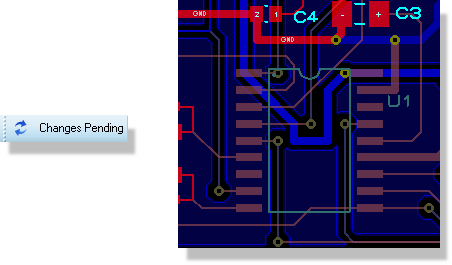
The deleted part and its tracking shown dimmed, with Changes Pending on the connectivity status widget
When you click on changes pending to accept the changes both the footprint and its tracking will be removed from the layout.
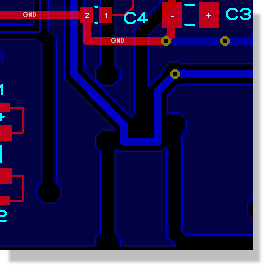
The layout after the pending changes have been accepted
Alternatively, an undo operation will revert both the schematic and the layout to their previous status.
Live Netlisting Off
When you delete the component from the schematic the layout module will enter a locked condition.
Deleting a component with live netlisting off locks the layout
When you click on the padlock to unlock the current connectivity is sent to the PCB layout. The deleted part and tracking will then appear dimmed and the connectivity status will indicate changes pending.
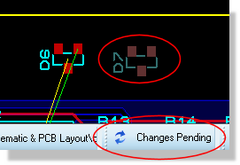
With live netlisting off, unlocking the layout dims the deleted part and raises Changes Pending
Clicking on changes pending will commit the deletion and the schematic and layout will be back in sync.
Removing a component or wire is an operation which affects objects that the board designer has already placed on the layout. As such, it requires you to manually confirm by clicking on the changes pending button to sync the layout.
If you find the dimmed state hard to see you can change the colour (e.g. bright yellow) from the View Menu > Edit Layer Colours/Visibility command (CTRL+L) in the layout module.
Changing the Connectivity
Live Netlisting On
Adding connectivity is an action which does not affect the existing tracking on the layout. A ratsnest line will appear in the PCB Module as soon as you complete the wire on the schematic and the system will automatically synchronise.
The effect of removing connections on the schematic depends on whether they have been tracked on the layout.
- If a connection is untracked on the layout (still a ratsnest line) then removing the connection on the schematic will simply remove the ratsnest line and the software will remain in sync.
- If a connection is tracked on the layout then removing the connection on the schematic will put the layout into a changes pending state and the corresponding track will appear in a dimmed state. Confirming the deletion by clicking on changes pending will remove the track and the software will return to a synchronised state. You can also choose to tag changes so that you can locate and examine on the layout before confirming the delete.
Live Netlisting Off
Any changes to connectivity will render the layout module in a locked state. When the editing is complete, clicking on the padlock icon to unlock the PCB will update the layout with the new connectivity information.
If the only changes were the addition of new connections then ratsnest lines will appear on the layout.
If connections were removed which involve existing tracking then the PCB will enter the changes pending state and the corresponding track(s) will appear in a dimmed state. Confirming the deletion by clicking on changes pending will remove the track and the software will return to a synchronised state.
Re-Annotating Components, and Re-Packaging Gates
Live Netlisting On
Re-annotating components is fully automatic. The layout will update and the system will remain in sync.
Gate-swapping multi-element parts from the schematic is also fully automatic. The layout will update and remain in sync.
Use the Global Annotator from the Tools menu on the schematic to automate the task on the schematic, or the Automatic Annotator from the Tools menu on the layout to automate the task according to your needs. Context sensitive help on both dialogues is available via the question mark at the top right of the dialogue form.
Live Netlisting Off
Re-annotating components will lock the layout. Unlocking the layout will auto-sync with the schematic.
Gate-swapping multi-element parts from the schematic will also lock the layout. Unlocking the layout will auto-sync with the schematic.
In either case above, the assumption is that you have only re-annotated or gate-swapped. Clearly, if you re-annotate, delete, add and re-wire then you will enter a changes pending state when you unlock the layout. The re-annotation changes however will be applied - confirming changes pending serves to confirm any removal operations from the layout.